Flop flip schematic pmos nmos inverters parallel vertically combination Ee 421l, fall 2018, lab project Flip flop explained electronics general
Proposed Positive edge D flip flop Circuits | Download Scientific Diagram
D flip flop circuit using hef4013b
Flop logic delay explained
Flop proposed tspc1 proposed d-ff circuit schematic of proposed d flip-flop is as shown Proposed positive edge d flip flop circuitsFlop flip circuit logic explained detail.
High frequency d flip flop for phase detectorFlip flop gates Flop flip frequency detector phase high cadence communityD flip flop [explained] in detail.

Flop circuits proposed
Vhdl tutorial 16: design a d flip-flop using vhdlFlop truth logic jk flops gates circuits clock 74hc00 clk latches input termed D flip flop explained in detailD-flip flop using transmission gates.
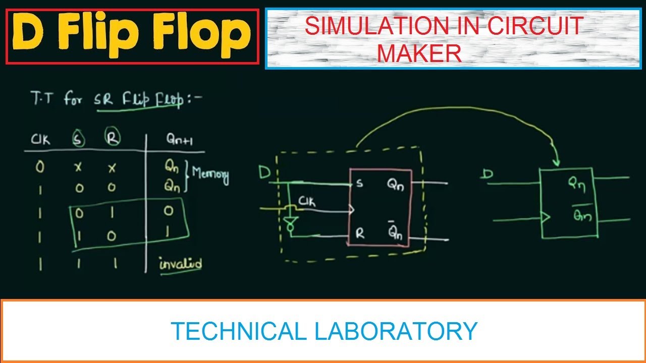
D flip flop || simulation in circuit maker .


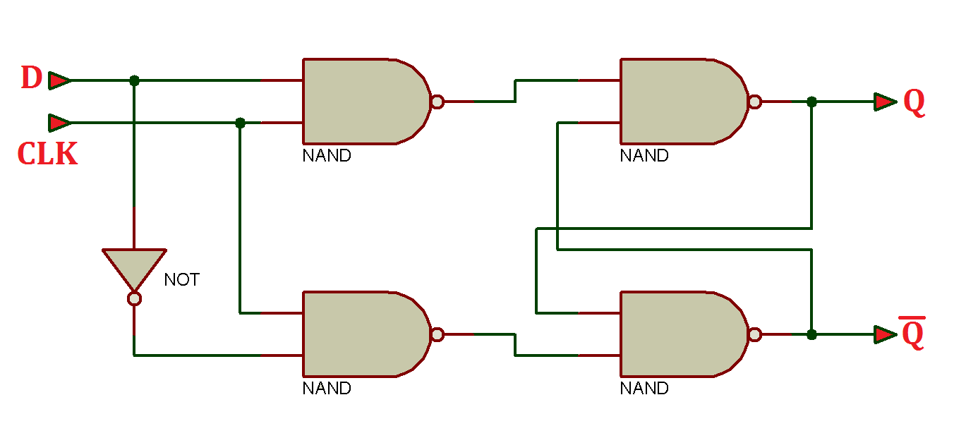


![D Flip Flop [Explained] in detail](https://i2.wp.com/eeeproject.com/wp-content/uploads/2017/09/D-flip-flop-logic-circuit.jpg?is-pending-load=1)

![D Flip Flop [Explained] in detail](https://i2.wp.com/eeeproject.com/wp-content/uploads/2017/09/D-flip-flop-logic-circuit.jpg?resize=552%2C316&ssl=1)